How Capacitors Work
What is a capacitor?
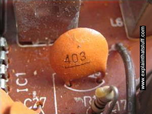
Photo: A small capacitor in a transistor radio circuit.
Take two electrical conductors (things that let electricity flow through them) and separate them with an insulator (a material that doesn't let electricity flow very well) and you make a capacitor: something that can store electrical energy. Adding electrical energy to a capacitor is called charging; releasing the energy from a capacitor is known as discharging.
A capacitor is a bit like a battery, but it has a different job to do. A battery uses chemicals to store electrical energy and release it very slowly through a circuit; sometimes (in the case of a quartz watch) it can take several years. A capacitor generally releases its energy much more rapidly—often in seconds or less. If you're taking a flash photograph, for example, you need your camera to produce a huge burst of light in a fraction of a second. A capacitor attached to the flash gun charges up for a few seconds using energy from your camera's batteries. (It takes time to charge a capacitor and that's why you typically have to wait a little while.) Once the capacitor is fully charged, it can release all that energy in an instant through the xenon flash bulb. Zap!
Capacitors come in all shapes and sizes, but they usually have the same basic components. There are the two conductors (known as plates, largely for historic reasons) and there's the insulator in between them (called the dielectric). The two plates inside a capacitor are wired to two electrical connections on the outside called terminals, which are like thin metal legs you can hook into an electric circuit.

Photo: Inside, an electrolytic capacitor is a bit like a Swiss roll. The "plates" are two very thin sheets of metal; the dielectric an oily plastic film in between them. The whole thing is wrapped up into a compact cylinder and coated in a protective metal case. WARNING: It can be dangerous to open up capacitors. First, they can hold very high voltages. Second, the dielectric is sometimes made of toxic or corrosive chemicals that can burn your skin.

Artwork: How an electrolytic capacitor is made by rolling up sheets of aluminum foil (gray) and a dielectric material (in this case, paper or thin cheesecloth soaked in an acid or other organic chemical). The foil sheets are connected to terminals (blue) on the top so the capacitor can be wired into a circuit. Artwork courtesy of US Patent and Trademark Office from US Patent 2,089,683: Electrical capacitor by Frank Clark, General Electric, August 10, 1937.
You can charge a capacitor simply by wiring it up into an electric circuit. When you turn on the power, an electric charge gradually builds up on the plates. One plate gains a positive charge and the other plate gains an equal and opposite (negative) charge. If you disconnect the power, the capacitor keeps hold of its charge (though it may slowly leak away over time). But if you connect the capacitor to a second circuit containing something like an electric motor or a flash bulb, charge will flow from the capacitor through the motor or lamp until there's none remaining on the plates.
Although capacitors effectively have only one job to do (storing charge), they can be put to all sorts of different uses in electrical circuits. They can be used as timing devices (because it takes a certain, predictable amount of time to charge them), as filters (circuits that allow only certain signals to flow), for smoothing the voltage in circuits, for tuning (in radios and TVs), and for a variety of other purposes. Large supercapacitors can also be used instead of batteries.
Capacitors and capacitance
The amount of electrical energy a capacitor can store is called its capacitance. The capacitance of a capacitor is a bit like the size of a bucket: the bigger the bucket, the more water it can store; the bigger the capacitance, the more electricity a capacitor can store. There are three ways to increase the capacitance of a capacitor. One is to increase the size of the plates. Another is to move the plates closer together. The third way is to make the dielectric as good an insulator as possible. Capacitors use dielectrics made from all sorts of materials. In transistor radios, the tuning is carried out by a large variable capacitor that has nothing but air between its plates. In most electronic circuits, the capacitors are sealed components with dielectrics made of ceramics such as mica and glass, paper soaked in oil, or plastics such as mylar.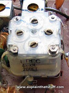
Photo: This variable capacitor is attached to the main tuning dial in a transistor radio. When you turn the dial with your finger, you turn an axle running through the capacitor. This rotates a set of thin metal plates so they overlap to a greater or lesser extent with another set of plates threaded in between them. The degree of overlap between the plates alters the capacitance and that's what tunes the radio into a particular station.
How do we measure capacitance?
The size of a capacitor is measured in units called farads (F), named for English electrical pioneer Michael Faraday (1791–1867). One farad is a huge amount of capacitance so, in practice, most of the capacitors we come across are just fractions of a farad—typically microfarads (millionths of a farad, written μF), nanofarads (thousand-millionths of a farad written nF), and picofarads (million millionths of a farad, written pF). Supercapacitors store far bigger charges, sometimes rated in thousands of farads.Why do capacitors store energy?
If you find capacitors mysterious and weird, and they don't really make sense to you, try thinking about gravity instead. Suppose you're standing at the bottom of some steps and you decide to start climbing. You have to heave your body up, against Earth's gravity, which is an attractive (pulling) force. As physicists say, you have to "do work" to climb a ladder (work against the force of gravity) and use energy. The energy you use isn't lost, but stored by your body as gravitational potential energy, which you could use to do other things (whizzing down a slide back to ground level, for example).What you do when you climb steps, ladders, mountains, or anything else is work against Earth's gravitational field. A very similar thing is going on in a capacitor. If you have a positive electrical charge and a negative electrical charge, they attract one another like the opposite poles of two magnets—or like your body and Earth. If you pull them apart, you have to "do work" against this electrostatic force. Again, just like with climbing steps, the energy you use isn't lost, but stored by the charges as they separate. This time it's called electrical potential energy. And this, if you've not guessed by now, is the energy that a capacitor stores. Its two plates hold opposite charges and the separation between them creates an electric field. That's why a capacitor stores energy.
Why do capacitors have two plates?
As we've already seen, capacitors have two conducting plates separated by an insulator. The bigger the plates, the closer they are, and the better the insulator in between them, the more charge a capacitor can store. But why are all these things true? Why don't capacitors just have one big plate? Let's try and find a simple and satisfying explanation.Suppose you have a big metal sphere mounted on an insulating, wooden stand. You can store a certain amount of electric charge on the sphere; the bigger it is (the bigger its radius), the more charge you can store, and the more charge you store, the bigger the potential (voltage) of the sphere. Eventually, though, you'll reach a point where if you add so much as a single extra electron (the smallest possible unit of charge), the capacitor will stop working. The air around it will break down, turning from an insulator to a conductor: charge will zap through the air to Earth (ground) or another nearby conductor as a spark—an electric current—in a mini bolt of lightning. The maximum amount of charge you can store on the sphere is what we mean by its capacitance. The voltage (V), charge (Q), and capacitance are related by a very simple equation:
C = Q/V
So the more charge you can store at a given voltage, without causing the
air to break down and spark, the higher the capacitance. If you could
somehow store more charge on the sphere without reaching the point
where you created a spark, you would effectively increase its
capacitance. How might you do that?Forget about the sphere. Suppose you have a flat metal plate with the maximum possible charge stored on it and you find the plate is at a certain voltage. If you bring a second identical plate up close to it, you'll find you can store much more charge on the first plate for the same voltage. That's because the first plate creates an electric field all around it that "induces" an equal and opposite charge on the second plate. The second plate therefore reduces the voltage of the first plate. We can now store more charge on the first plate without causing a spark. We can keep on doing that until we reach the original voltage. With more charge (Q) stored for exactly the same voltage (V), the equation C = Q/V tells us that we've increased the capacitance of our charge storing device by adding a second plate, and this is essentially why capacitors have two plates and not one. In practice, the extra plate makes a huge difference—which is why all practical capacitors have two plates.
How can we increase the capacitance?
It's intuitively obvious that if you make the plates bigger, you'll be able to store more charge (just as if you make a closet bigger you can stuff more things inside it). So increasing the area of the plates also increases the capacitance. Less obviously, if we reduce the distance between the plates, that also increases the capacitance. That's because the shorter the distance between the plates, the more effect the plates have on one another. The second plate, being closer, reduces the potential of the first plate even more, and that increases the capacitance.
Artwork: A dielectric increases the capacitance of a capacitor by reducing the electric field between its plates, so reducing the potential (voltage) of each plate. That means you can store more charge on the plates at the same voltage. The electric field in this capacitor runs from the positive plate on the left to the negative plate on the right. Because opposite charges attract, the polar molecules (grey) of the dielectric line up in the opposite way—and this is what reduces the field.
The final thing we thing we can do to increase the capacitance is to change the dielectric (the material between the plates). Air works pretty well, but other materials are even better. Glass is at least 5 times more effective than air, which is why the earliest capacitors (Leyden jars, using ordinary glass as the dielectric) worked so well, but it's heavy, impractical, and hard to squeeze into small spaces. Waxed paper is about 4 times better than air, very thin, cheap, easy to make in large pieces, and easy to roll, which makes it an excellent, practical dielectric. The best dielectric materials are made of polar molecules (ones with more positive electric charge on one side and more negative electric charge on the other). When they sit in the electric field between two capacitor plates, they line up with their charges pointing opposite to the field, which effectively reduces it. That reduces the potential on the plates and, as before, increases their capacitance. Theoretically, water, which is made of really tiny polar molecules, would make an excellent dielectric, roughly 80 times better than air. Practically, though, it's not so good (it leaks and dries out and changes from a liquid to ice or steam at relatively modest temperatures), so it's not used in real capacitors.

In this article, we'll learn exactly what a capacitor is, what it does and how it's used in electronics. We'll also look at the history of the capacitor and how several people helped shape its progress.
In theory, the dielectric can be any non-conductive substance. However, for practical applications, specific materials are used that best suit the capacitor's function. Mica, ceramic, cellulose, porcelain, Mylar, Teflon and even air are some of the non-conductive materials used. The dielectric dictates what kind of capacitor it is and for what it is best suited. Depending on the size and type of dielectric, some capacitors are better for high frequency uses, while some are better for high voltage applications. Capacitors can be manufactured to serve any purpose, from the smallest plastic capacitor in your calculator, to an ultra capacitor that can power a commuter bus. NASA uses glass capacitors to help wake up the space shuttle's circuitry and help deploy space probes. Here are some of the various types of capacitors and how they are used.
- Air - Often used in radio tuning circuits
- Mylar - Most commonly used for timer circuits like clocks, alarms and counters
- Glass - Good for high voltage applications
- Ceramic - Used for high frequency purposes like antennas, X-ray and MRI machines
- Super capacitor - Powers electric and hybrid cars

