How Transistors Work – A Simple Explanation
The
output Vo depends on V, R1 and R2. For example if V = 100V, R1 = 40
Ohms and R2 = 60 Ohms. Then Vo = V * (R2/(R1+R2) = 100 * (60/100) = 60V.
By changing the values of V, R1 and R2 the output Vo can be changed.
Now let us change the resistor R2 with a Variable Resistor.
In
the above circuit V and R1 are fixed and R2 is a variable. So, if we
change R2, Vo will change. We generally call this as Regulator. Now let
us have a variable resistor whose resistance can be changed by the
voltage instead of manual control.
In
the above circuit the value of R2 is changed by the voltage Vi. If we
change Vi then Vo is changed. The relation between Vo and Vi is called
Amplification Factor. Here is a surprise. The resistor who's resistance
is changed by voltage (current) is nothing but a Transistor.
Actually
Transistor acts as only a variable resistor. The value of resistor
between Collector and Emitter is changed by the base current.
The Transistor acts as a Regulator (Variable Resistor) or a switch(ON/OFF).
The Transistor has 3 operating modes.
1. Cut-off (Switch - OFF)
2- Saturation (Switch - ON)
3- Active (Regulator).
2- Saturation (Switch - ON)
3- Active (Regulator).
1. Cut-off Mode
Vb < Vbe (Generally 0.7V)
So Ib = 0A
Ic = 0A
Vc = Ic x Rc = 0V
Vo = Vcc - Vc = Vcc
So Ib = 0A
Ic = 0A
Vc = Ic x Rc = 0V
Vo = Vcc - Vc = Vcc
2. Saturation Mode
Ic > Ic.max
Ic.max = Vcc/Rc
Ic = β Ib
Ic = Ic.max
Vc = Ic x Rc = Vcc
Vo = Vcc - Vc = 0V
Ic.max = Vcc/Rc
Ic = β Ib
Ic = Ic.max
Vc = Ic x Rc = Vcc
Vo = Vcc - Vc = 0V
3. Active Mode
0 < Ic < Ic.max
Ib = (Vb - Vbe)/Rb
Ic = β x Ib
Vc = Ic x Rc
Vo = Vcc - Vc
0V < Vo < Vcc
Ic = β x Ib
Vc = Ic x Rc
Vo = Vcc - Vc
0V < Vo < Vcc
When a Transistor acts as a Regulator, it is called an Amplifier.
When a Transistor acts as a Switch, it is called a Gate.
When a Transistor acts as a Switch, it is called a Gate.
Transistor in Active Mode - Analog Electronics
Transistor in Cutoff/Saturation Mode - Digital Electronics
You can get more detailed information from the answer to the following question.
Transistor in Cutoff/Saturation Mode - Digital Electronics
You can get more detailed information from the answer to the following question.
"Energy can neither be created nor be destroyed"
The problem is that almost everyone is trying to teach that a transistor is “…a semiconductor device”. And instead of just telling you what it does, they explain that “…it consists of n-doped and p-doped materials”.
I don’t know about you, but that statement didn’t help me much!
So let me tell you, in a simple way, how transistors work. I even made a video for you, just to make it clearer.
The transistor is like an electronic switch. It can turn a current on and off. A simple way you can think of it is to look at the transistor as a relay without any moving parts. A transistor is similar to a relay in the sense that you can use it to turn something ON and OFF.
Check out the video explanation I made on the transistor:
There are different types of transistors. A very common one is the “bipolar junction transistor” or “BJT”. And it usually looks like this:
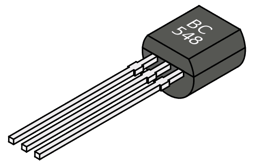
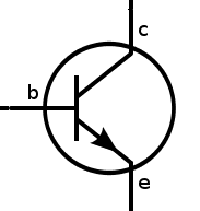
It has three pins: Base (b), collector (c) and emitter (e). And it comes in two versions: NPN and PNP. The schematic symbol for the NPN looks like this:
How transistors work
The transistor works because of something called a semiconducting material. A current flowing from the base to the emitter “opens” the flow of current from the collector to the emitter.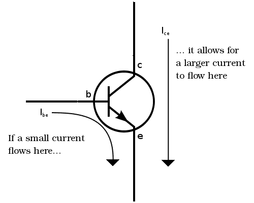
In a standard NPN transistor, you need to apply a voltage of about 0.7V between the base and the emitter to get the current flowing from base to emitter. When you apply 0.7V from base to emitter you will turn the transistor ON and allow a current to flow from collector to emitter.
Let’s look at an example:
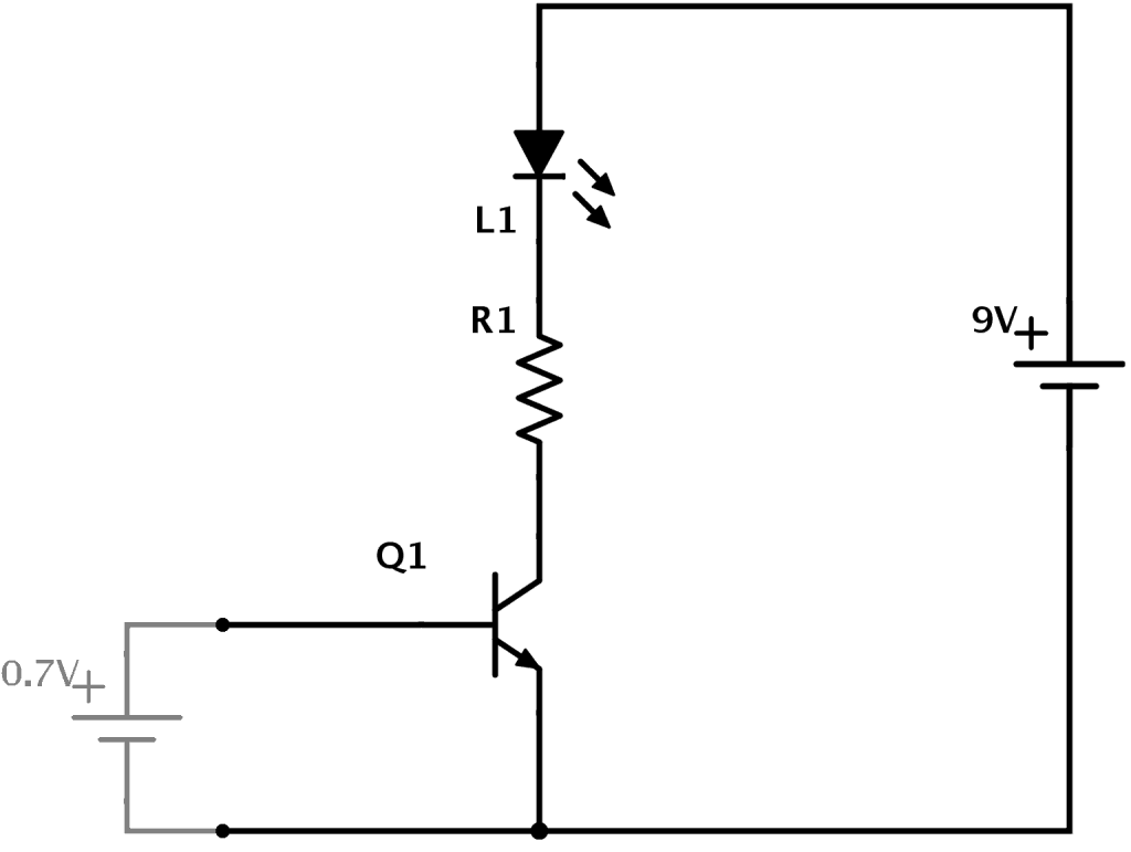
In the example above you can see how transistors work. A 9V battery connects to an LED and a resistor. But it connects through the transistor. This means that no current will flow in that part of the circuit until the transistor turns ON.
To turn the transistor ON you need to apply 0.7V from base to emitter of the transistor. Imagine you have a small 0.7V battery. (In a practical circuit you would use resistors to get the correct voltage from whatever voltage source you have)
When you apply the 0.7V battery from base to emitter, the transistor turns ON. This allows current to flow from the collector to the emitter. And thereby turning the LED ON!
More on the transistor
In this article, I explained the NPN transistor that turns ON when you have a voltage on the base. There is also a transistor called PNP which works in the opposite way. Check out my article PNP Transistor – How Does It Work? to learn more.The transistor is also what makes amplifiers work. Instead of having just two states (on or off) it can also be anywhere in between “fully on” and “fully off”.
A small “control current” can then control how big a portion of a bigger “main current” that is going to flow through it. Thereby, the transistor can amplify a signal.
We use transistors in almost all electronics and it’s probably the most important component in electronics.
Do you understand how transistors work? Post your comments and questions below! Then go check out the LDR circuit diagram and see if you can understand it.
No comments:
Post a Comment