Wednesday, October 17, 2018

How Capacitors Work


What is a capacitor?

Small mica capacitor in a transistor radio.
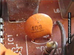
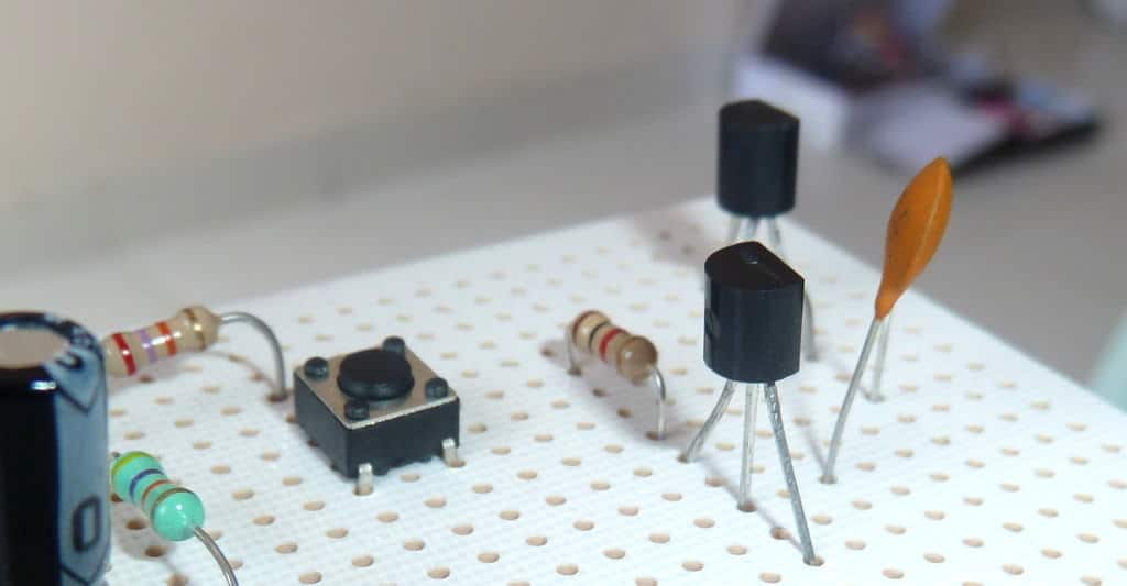
Photo: A small capacitor in a transistor radio circuit.
Take two electrical conductors (things that let electricity flow through them) and separate them with an insulator (a material that doesn't let electricity flow very well) and you make a capacitor: something that can store electrical energy. Adding electrical energy to a capacitor is called charging; releasing the energy from a capacitor is known as discharging.
A capacitor is a bit like a battery, but it has a different job to do. A battery uses chemicals to store electrical energy and release it very slowly through a circuit; sometimes (in the case of a quartz watch) it can take several years. A capacitor generally releases its energy much more rapidly—often in seconds or less. If you're taking a flash photograph, for example, you need your camera to produce a huge burst of light in a fraction of a second. A capacitor attached to the flash gun charges up for a few seconds using energy from your camera's batteries. (It takes time to charge a capacitor and that's why you typically have to wait a little while.) Once the capacitor is fully charged, it can release all that energy in an instant through the xenon flash bulb. Zap!
Capacitors come in all shapes and sizes, but they usually have the same basic components. There are the two conductors (known as plates, largely for historic reasons) and there's the insulator in between them (called the dielectric). The two plates inside a capacitor are wired to two electrical connections on the outside called terminals, which are like thin metal legs you can hook into an electric circuit.
The inside of an electrolytic capacitor
Photo: Inside, an electrolytic capacitor is a bit like a Swiss roll. The "plates" are two very thin sheets of metal; the dielectric an oily plastic film in between them. The whole thing is wrapped up into a compact cylinder and coated in a protective metal case. WARNING: It can be dangerous to open up capacitors. First, they can hold very high voltages. Second, the dielectric is sometimes made of toxic or corrosive chemicals that can burn your skin.
How an electrolytic capacitor is made from a Swiss roll of metal film with a dielectric in between.
Artwork: How an electrolytic capacitor is made by rolling up sheets of aluminum foil (gray) and a dielectric material (in this case, paper or thin cheesecloth soaked in an acid or other organic chemical). The foil sheets are connected to terminals (blue) on the top so the capacitor can be wired into a circuit. Artwork courtesy of US Patent and Trademark Office from US Patent 2,089,683: Electrical capacitor by Frank Clark, General Electric, August 10, 1937.
You can charge a capacitor simply by wiring it up into an electric circuit. When you turn on the power, an electric charge gradually builds up on the plates. One plate gains a positive charge and the other plate gains an equal and opposite (negative) charge. If you disconnect the power, the capacitor keeps hold of its charge (though it may slowly leak away over time). But if you connect the capacitor to a second circuit containing something like an electric motor or a flash bulb, charge will flow from the capacitor through the motor or lamp until there's none remaining on the plates.
Although capacitors effectively have only one job to do (storing charge), they can be put to all sorts of different uses in electrical circuits. They can be used as timing devices (because it takes a certain, predictable amount of time to charge them), as filters (circuits that allow only certain signals to flow), for smoothing the voltage in circuits, for tuning (in radios and TVs), and for a variety of other purposes. Large supercapacitors can also be used instead of batteries.

Capacitors and capacitance

The amount of electrical energy a capacitor can store is called its capacitance. The capacitance of a capacitor is a bit like the size of a bucket: the bigger the bucket, the more water it can store; the bigger the capacitance, the more electricity a capacitor can store. There are three ways to increase the capacitance of a capacitor. One is to increase the size of the plates. Another is to move the plates closer together. The third way is to make the dielectric as good an insulator as possible. Capacitors use dielectrics made from all sorts of materials. In transistor radios, the tuning is carried out by a large variable capacitor that has nothing but air between its plates. In most electronic circuits, the capacitors are sealed components with dielectrics made of ceramics such as mica and glass, paper soaked in oil, or plastics such as mylar.
Variable capacitor in a radio tuning control
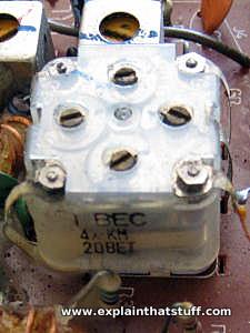
Photo: This variable capacitor is attached to the main tuning dial in a transistor radio. When you turn the dial with your finger, you turn an axle running through the capacitor. This rotates a set of thin metal plates so they overlap to a greater or lesser extent with another set of plates threaded in between them. The degree of overlap between the plates alters the capacitance and that's what tunes the radio into a particular station.

How do we measure capacitance?

The size of a capacitor is measured in units called farads (F), named for English electrical pioneer Michael Faraday (1791–1867). One farad is a huge amount of capacitance so, in practice, most of the capacitors we come across are just fractions of a farad—typically microfarads (millionths of a farad, written μF), nanofarads (thousand-millionths of a farad written nF), and picofarads (million millionths of a farad, written pF). Supercapacitors store far bigger charges, sometimes rated in thousands of farads.

Why do capacitors store energy?

If you find capacitors mysterious and weird, and they don't really make sense to you, try thinking about gravity instead. Suppose you're standing at the bottom of some steps and you decide to start climbing. You have to heave your body up, against Earth's gravity, which is an attractive (pulling) force. As physicists say, you have to "do work" to climb a ladder (work against the force of gravity) and use energy. The energy you use isn't lost, but stored by your body as gravitational potential energy, which you could use to do other things (whizzing down a slide back to ground level, for example).
What you do when you climb steps, ladders, mountains, or anything else is work against Earth's gravitational field. A very similar thing is going on in a capacitor. If you have a positive electrical charge and a negative electrical charge, they attract one another like the opposite poles of two magnets—or like your body and Earth. If you pull them apart, you have to "do work" against this electrostatic force. Again, just like with climbing steps, the energy you use isn't lost, but stored by the charges as they separate. This time it's called electrical potential energy. And this, if you've not guessed by now, is the energy that a capacitor stores. Its two plates hold opposite charges and the separation between them creates an electric field. That's why a capacitor stores energy.

Why do capacitors have two plates?

As we've already seen, capacitors have two conducting plates separated by an insulator. The bigger the plates, the closer they are, and the better the insulator in between them, the more charge a capacitor can store. But why are all these things true? Why don't capacitors just have one big plate? Let's try and find a simple and satisfying explanation.
Suppose you have a big metal sphere mounted on an insulating, wooden stand. You can store a certain amount of electric charge on the sphere; the bigger it is (the bigger its radius), the more charge you can store, and the more charge you store, the bigger the potential (voltage) of the sphere. Eventually, though, you'll reach a point where if you add so much as a single extra electron (the smallest possible unit of charge), the capacitor will stop working. The air around it will break down, turning from an insulator to a conductor: charge will zap through the air to Earth (ground) or another nearby conductor as a spark—an electric current—in a mini bolt of lightning. The maximum amount of charge you can store on the sphere is what we mean by its capacitance. The voltage (V), charge (Q), and capacitance are related by a very simple equation:
C = Q/V
So the more charge you can store at a given voltage, without causing the air to break down and spark, the higher the capacitance. If you could somehow store more charge on the sphere without reaching the point where you created a spark, you would effectively increase its capacitance. How might you do that?
Forget about the sphere. Suppose you have a flat metal plate with the maximum possible charge stored on it and you find the plate is at a certain voltage. If you bring a second identical plate up close to it, you'll find you can store much more charge on the first plate for the same voltage. That's because the first plate creates an electric field all around it that "induces" an equal and opposite charge on the second plate. The second plate therefore reduces the voltage of the first plate. We can now store more charge on the first plate without causing a spark. We can keep on doing that until we reach the original voltage. With more charge (Q) stored for exactly the same voltage (V), the equation C = Q/V tells us that we've increased the capacitance of our charge storing device by adding a second plate, and this is essentially why capacitors have two plates and not one. In practice, the extra plate makes a huge difference—which is why all practical capacitors have two plates.

How can we increase the capacitance?

It's intuitively obvious that if you make the plates bigger, you'll be able to store more charge (just as if you make a closet bigger you can stuff more things inside it). So increasing the area of the plates also increases the capacitance. Less obviously, if we reduce the distance between the plates, that also increases the capacitance. That's because the shorter the distance between the plates, the more effect the plates have on one another. The second plate, being closer, reduces the potential of the first plate even more, and that increases the capacitance.
A dielectric increases the charge a capacitor can store by reducing the electric field between its plates.
Artwork: A dielectric increases the capacitance of a capacitor by reducing the electric field between its plates, so reducing the potential (voltage) of each plate. That means you can store more charge on the plates at the same voltage. The electric field in this capacitor runs from the positive plate on the left to the negative plate on the right. Because opposite charges attract, the polar molecules (grey) of the dielectric line up in the opposite way—and this is what reduces the field.
The final thing we thing we can do to increase the capacitance is to change the dielectric (the material between the plates). Air works pretty well, but other materials are even better. Glass is at least 5 times more effective than air, which is why the earliest capacitors (Leyden jars, using ordinary glass as the dielectric) worked so well, but it's heavy, impractical, and hard to squeeze into small spaces. Waxed paper is about 4 times better than air, very thin, cheap, easy to make in large pieces, and easy to roll, which makes it an excellent, practical dielectric. The best dielectric materials are made of polar molecules (ones with more positive electric charge on one side and more negative electric charge on the other). When they sit in the electric field between two capacitor plates, they line up with their charges pointing opposite to the field, which effectively reduces it. That reduces the potential on the plates and, as before, increases their capacitance. Theoretically, water, which is made of really tiny polar molecules, would make an excellent dielectric, roughly 80 times better than air. Practically, though, it's not so good (it leaks and dries out and changes from a liquid to ice or steam at relatively modest temperatures), so it's not used in real capacitors.
Bar chart comparing the relative permittivities of 10 different dielectric materials.
Chart: Different materials make better or worse dielectrics according to how well they insulate the space between a capacitor's plates and reduce the electric field between them. A measurement called the relative permittivity tells us how good a dielectric something will make. A vacuum is the worst dielectric and is given a relative permittivity of 1. Other dielectrics are measured relative (by comparing them) to a vacuum. Air is roughly the same. Paper is about 3 times better. Alcohol and water, which have polar molecules, make particularly good dielectrics.


Flash capacitor from a point-and-shoot camera.  Take the capacitor quiz to learn more.
Flash capacitor from a point-and-shoot camera.
In a way, a capacitor is a little like a battery. Although they work in completely different ways, capacitors and batteries both store electrical energy. If you have read How Batteries Work, then you know that a battery has two terminals. Inside the battery, chemical reactions produce electrons on one terminal and absorb electrons on the other terminal. A capacitor is much simpler than a battery, as it can't produce new electrons -- it only stores them.
In this article, we'll learn exactly what a capacitor is, what it does and how it's used in electronics. We'll also look at the history of the capacitor and how several people helped shape its progress.
Inside the capacitor, the terminals connect to two metal plates separated by a non-conducting substance, or dielectric. You can easily make a capacitor from two pieces of aluminum foil and a piece of paper. It won't be a particularly good capacitor in terms of its storage capacity, but it will work.
In theory, the dielectric can be any non-conductive substance. However, for practical applications, specific materials are used that best suit the capacitor's function. Mica, ceramic, cellulose, porcelain, Mylar, Teflon and even air are some of the non-conductive materials used. The dielectric dictates what kind of capacitor it is and for what it is best suited. Depending on the size and type of dielectric, some capacitors are better for high frequency uses, while some are better for high voltage applications. Capacitors can be manufactured to serve any purpose, from the smallest plastic capacitor in your calculator, to an ultra capacitor that can power a commuter bus. NASA uses glass capacitors to help wake up the space shuttle's circuitry and help deploy space probes. Here are some of the various types of capacitors and how they are used.
  • Air - Often used in radio tuning circuits
  • Mylar - Most commonly used for timer circuits like clocks, alarms and counters
  • Glass - Good for high voltage applications
  • Ceramic - Used for high frequency purposes like antennas, X-ray and MRI machines
  • Super capacitor - Powers electric and hybrid cars
In the next section, we'll take a closer look at exactly how capacitors work.

How Transistors Work – A Simple Explanation


To understand how an amplifier works, you need to first understand how a Voltage Divider circuit functions. Below is a simple Voltage Divider Circuit.
The output Vo depends on V, R1 and R2. For example if V = 100V, R1 = 40 Ohms and R2 = 60 Ohms. Then Vo = V * (R2/(R1+R2) = 100 * (60/100) = 60V. By changing the values of V, R1 and R2 the output Vo can be changed. Now let us change the resistor R2 with a Variable Resistor.
In the above circuit V and R1 are fixed and R2 is a variable. So, if we change R2, Vo will change. We generally call this as Regulator. Now let us have a variable resistor whose resistance can be changed by the voltage instead of manual control.
In the above circuit the value of R2 is changed by the voltage Vi. If we change Vi then Vo is changed. The relation between Vo and Vi is called Amplification Factor. Here is a surprise. The resistor who's resistance is changed by voltage (current) is nothing but a Transistor.
Actually Transistor acts as only a variable resistor. The value of resistor between Collector and Emitter is changed by the base current.
The Transistor acts as a Regulator (Variable Resistor) or a switch(ON/OFF).
The Transistor has 3 operating modes.
1. Cut-off (Switch - OFF)
 2- Saturation (Switch - ON)
 3- Active (Regulator).
1. Cut-off Mode
Vb < Vbe (Generally 0.7V)
 So Ib = 0A
 Ic = 0A
 Vc = Ic x Rc = 0V
 Vo = Vcc - Vc = Vcc
2. Saturation Mode
Ic > Ic.max
 Ic.max = Vcc/Rc
 Ic = β Ib
Ic = Ic.max
 Vc = Ic x Rc = Vcc
 Vo = Vcc - Vc = 0V
3. Active Mode
0 < Ic < Ic.max
Ib = (Vb - Vbe)/Rb
 Ic = β x Ib
 Vc = Ic x Rc
 Vo = Vcc - Vc

 0V < Vo < Vcc
When a Transistor acts as a Regulator, it is called an Amplifier.
 When a Transistor acts as a Switch, it is called a Gate.
Transistor in Active Mode - Analog Electronics
 Transistor in Cutoff/Saturation Mode - Digital Electronics

 You can get more detailed information from the answer to the following question.

"Energy can neither be created nor be destroyed"

How transistors work is probably the hardest concept for you to understand as a beginner. At least it was for me.
The problem is that almost everyone is trying to teach that a transistor is “…a semiconductor device”. And instead of just telling you what it does, they explain that “…it consists of n-doped and p-doped materials”.
I don’t know about you, but that statement didn’t help me much!
So let me tell you, in a simple way, how transistors work. I even made a video for you, just to make it clearer.

transistor-in-a-circuit-2
The transistor is like an electronic switch. It can turn a current on and off. A simple way you can think of it is to look at the transistor as a relay without any moving parts. A transistor is similar to a relay in the sense that you can use it to turn something ON and OFF.
FREE Bonus: Download Basic Electronic Components [PDF] – a mini eBook with examples that will teach you how the basic components of electronics work.
Check out the video explanation I made on the transistor:

There are different types of transistors. A very common one is the “bipolar junction transistor” or “BJT”. And it usually looks like this:
A common NPN transistor
It has three pins: Base (b), collector (c) and emitter (e). And it comes in two versions: NPN and PNP. The schematic symbol for the NPN looks like this:
Schematic symbol of an NPN transistor with pin names

How transistors work

The transistor works because of something called a semiconducting material. A current flowing from the base to the emitter “opens” the flow of current from the collector to the emitter.
Explanation of how transistors work
In a standard NPN transistor, you need to apply a voltage of about 0.7V between the base and the emitter to get the current flowing from base to emitter. When you apply 0.7V from base to emitter you will turn the transistor ON and allow a current to flow from collector to emitter.

Let’s look at an example:

How a transistor works in a circuit
In the example above you can see how transistors work. A 9V battery connects to an LED and a resistor. But it connects through the transistor. This means that no current will flow in that part of the circuit until the transistor turns ON.
To turn the transistor ON you need to apply 0.7V from base to emitter of the transistor. Imagine you have a small 0.7V battery. (In a practical circuit you would use resistors to get the correct voltage from whatever voltage source you have)
When you apply the 0.7V battery from base to emitter, the transistor turns ON. This allows current to flow from the collector to the emitter. And thereby turning the LED ON!

More on the transistor

In this article, I explained the NPN transistor that turns ON when you have a voltage on the base. There is also a transistor called PNP which works in the opposite way. Check out my article PNP Transistor – How Does It Work? to learn more.
The transistor is also what makes amplifiers work. Instead of having just two states (on or off) it can also be anywhere in between “fully on” and “fully off”.
A small “control current” can then control how big a portion of a bigger “main current” that is going to flow through it. Thereby, the transistor can amplify a signal.
We use transistors in almost all electronics and it’s probably the most important component in electronics.
Do you understand how transistors work? Post your comments and questions below! Then go check out the LDR circuit diagram and see if you can understand it.

Monday, October 15, 2018

how a transformer works

click on this video to see the animation of how a transformer works


PARTS AND MATERIALS
  • Steel flat bar, 4 pieces
  • Miscellaneous bolts, nuts, washers
  • 28 gauge “magnet” wire
  • Low-voltage AC power supply

“Magnet wire” is small-gauge wire insulated with a thin enamel coating. It is intended to be used to make electromagnets, because many “turns” of wire may be wrapped in a relatively small-diameter coil. Any gauge of wire will work, but 28 gauge is recommended so as to make a coil with as many turns as possible in a small diameter.

CROSS-REFERENCES
Lessons In Electric Circuits, Volume 2, chapter 9: “Transformers”

LEARNING OBJECTIVES
  • Effects of electromagnetism.
  • Effects of electromagnetic induction.
  • Effects of magnetic coupling on voltage regulation.
  • Effects of a winding turn on “step” ratio.

SCHEMATIC DIAGRAM


ILLUSTRATION


INSTRUCTIONS
Wrap two, equal-length bars of steel with a thin layer of electrically-insulating tape. Wrap several hundred turns of magnet wire around these two bars. You may make these windings with an equal or unequal number of turns, depending on whether or not you want the transformer to be able to “step” voltage up or down. I recommend equal turns, to begin with, then experiment later with coils of unequal turn count.
Join those bars together in a rectangle with two other, shorter, bars of steel. Use bolts to secure the bars together (it is recommended that you drill bolt holes through the bars before you wrap the wire around them).
Check for shorted windings (ohmmeter reading between wire ends and steel bar) after you’re finished wrapping the windings. There should be no continuity (infinite resistance) between the winding and the steel bar. Check for continuity between winding ends to ensure that the wire isn’t broken open somewhere within the coil. If either resistance measurements indicate a problem, the winding must be re-made.
Power your transformer with the low-voltage output of the “power supply” described at the beginning of this chapter. Do not power your transformer directly from wall-socket voltage (120 volts), as your home-made windings really aren’t rated for any significant voltage!
Measure the output voltage (secondary winding) of your transformer with an AC voltmeter. Connect a load of some kind (light bulbs are good!) to the secondary winding and re-measure voltage. Note the degree of voltage “sag” at the secondary winding as the load current is increased.

Loosen or remove the connecting bolts from one of the short bar pieces, thus increasing the reluctance (analogous to resistance) of the magnetic “circuit” coupling the two windings together. Note the effect on the output voltage and voltage “sag” under load.
If you’ve made your transformer with unequal-turn windings. try it in step-up versus step-down mode, powering different AC loads.


Saturday, October 13, 2018


Standard Resistor Values and Color

Components and wires are coded with colors to identify their value and function.

Image result for how to read a resistor and resistor colour code

The colors brown, red, green, blue, and violet are used as tolerance codes on 5-band resistors only. All 5-band resistors use a colored tolerance band. The blank (20%) “band” is only used with the “4-band” code (3 colored bands + a blank “band”).


Example #1


A resistor colored Yellow-Violet-Orange-Gold would be 47 kΩ with a tolerance of +/- 5%.

Example #2


A resistor colored Green-Red-Gold-Silver would be 5.2 Ω with a tolerance of +/- 10%.

Example #3


A resistor colored White-Violet-Black would be 97 Ω with a tolerance of +/- 20%. When you see only three color bands on a resistor, you know that it is actually a 4-band code with a blank (20%) tolerance band.

Example #4


A resistor colored Orange-Orange-Black-Brown-Violet would be 3.3 kΩ with a tolerance of +/- 0.1%.

Example #5


A resistor colored Brown-Green-Grey-Silver-Red would be 1.58 Ω with a tolerance of +/- 2%.

Example #6


A resistor colored Blue-Brown-Green-Silver-Blue would be 6.15 Ω with a tolerance of +/- 0.25%.

Preferred Values or E-series

To make mass manufacturing of resistors easier, the IEC (International Electrotechnical Commision) defined tolerance and resistance values for resistors in 1952. These are referred to as preferred values or E-series, published in standard IEC 60063:1963. Capactors, Zener diodes, and inductors also use these standards.

The purpose of this was so that when companies produce resistors with different values of resistance, they would equally space on a logarithmic scale. This helps the supplier with stocking different values. Resistors produced by different manufacturers are compatible for the same designs because of the use of standard values.


Standard Resistor Value Series and Tolerances


The standard E3, E6, E12, E24, E48 and E96 resistor values are listed below.


*The calculated tolerance for this series is 36.60%, While the standard only specifies a tolerance greater than 20%, other sources indicate 40% or 50%.

E3 Resistor Series

These are the most widely used resistor series in the electronics industry.

E6 Resistor Series

E12 Resistor Series

E24 Resistor Series

E48 Resistor Series


 how to test a transistor

Step 1: Materials

Well I had most of these materials on had so this project did not cost me a dime but if your lucky like me I'm sure you could get everything for under $5 if you scavenge for old components. Everything here is cheap and should be found locally in old electronics except for the 9 volt battery which I happen to have a case of. However the case was made out of bendable plastic sheets that I got from my art class if your creative you can make the case out of anything.

Stuff Needed:
  • LED of any color
  • 9 volt battery
  • bendable material to make the case
  • 3-4 pin socket for transistor
  • 10k ohm resistor
  • 470 ohm resistor
  • NPN transistors
  • Small Switch

Step 2: Testing

Before any electronic project goes to soldering or finalization you should always check with a breadboard that everything is working and that all the components are fine. This 5min check could save you from frustration later on after spending show much time soldering it to together to find out that your contraption doesn't even work.

Step 3: Construction

Now we will start of by soldering the components together just follow the circuit that has been attach and you will continue on until your done. You can choose to do it on a circuit board but for simplicity sake I just did it with out a circuit board and positions the joints in a way that wont allow for short circuits win place in their casing.

The transistor circuit I found was used as a way to learn transistors I just modified the circuit by allowing the transistor to be removable therefore leading to the circuit now becoming a transistor tester. 

Step 4: Casing

I made the case by first printing out the scaled up template I designed for a portable use. I printed out the sheet and then laid it below the plastic material. I basically traced out the case with an knife, and then glued it back up together with hot melt.
 

Okay at this point I hot melt the circuit components in to pre-cut openings and I was constantly checking the connections to make sure everything was in order by having the transistor in the place lighting up the LED the  whole the time. You would hate for a fault in the wiring after you closed everything back up with hot melt.

Step 5: YAY Finish

Okay that's it and everything should be in order now. This is first in a series of instructables that are soon to come.
Thank you for your time and if you have any comments feel free to tell me.

learn also how to read a resistor colour code simple and easy


Monday, October 8, 2018

              YOTECH ELECTRICAL/ELECTRONICS

we install/maintain the following