Standard Resistor Values and Color
Components and wires are coded with colors to identify their value and function.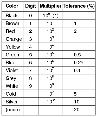
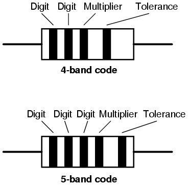
The colors brown, red, green, blue, and violet are used as tolerance codes on 5-band resistors only. All 5-band resistors use a colored tolerance band. The blank (20%) “band” is only used with the “4-band” code (3 colored bands + a blank “band”).
Example #1

A resistor colored Yellow-Violet-Orange-Gold would be 47 kΩ with a tolerance of +/- 5%.
Example #2
A resistor colored Green-Red-Gold-Silver would be 5.2 Ω with a tolerance of +/- 10%.
Example #3

A resistor colored White-Violet-Black would be 97 Ω with a tolerance of +/- 20%. When you see only three color bands on a resistor, you know that it is actually a 4-band code with a blank (20%) tolerance band.
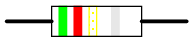
Example #4

A resistor colored Orange-Orange-Black-Brown-Violet would be 3.3 kΩ with a tolerance of +/- 0.1%.
Example #5
A resistor colored Brown-Green-Grey-Silver-Red would be 1.58 Ω with a tolerance of +/- 2%.
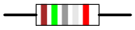
Example #6
A resistor colored Blue-Brown-Green-Silver-Blue would be 6.15 Ω with a tolerance of +/- 0.25%.
Preferred Values or E-series
To make mass manufacturing of resistors easier, the IEC (International Electrotechnical Commision) defined tolerance and resistance values for resistors in 1952. These are referred to as preferred values or E-series, published in standard IEC 60063:1963. Capactors, Zener diodes, and inductors also use these standards.The purpose of this was so that when companies produce resistors with different values of resistance, they would equally space on a logarithmic scale. This helps the supplier with stocking different values. Resistors produced by different manufacturers are compatible for the same designs because of the use of standard values.
Standard Resistor Value Series and Tolerances
The standard E3, E6, E12, E24, E48 and E96 resistor values are listed below.
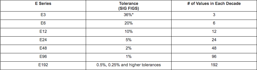
*The calculated tolerance for this series is 36.60%, While the standard only specifies a tolerance greater than 20%, other sources indicate 40% or 50%.
E3 Resistor Series
These are the most widely used resistor series in the electronics industry.
E6 Resistor Series

E12 Resistor Series

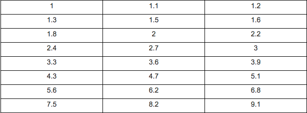
E24 Resistor Series
E48 Resistor Series


